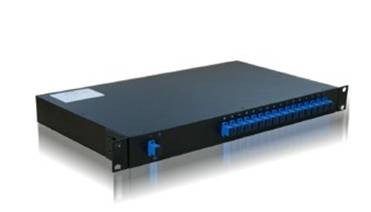
波分复用器
DWDM system
Description
Dense Wavelength Division Multiplexing, or DWDM for short, refers originally to optical signals multiplexed within the 1550-nm band so as to leverage the capabilities (and cost) of erbium doped fiber amplifiers (EDFAs), which are effective for wavelengths between approximately 1525-1565 nm (C band), or 1570-1610 nm (L band). There is also passive DWDM systems that become more and more popular amoung ISPs for their backbone line construction. EDFAs were originally developed to replace SONET/SDH optical-electrical-optical (OEO) regenerators, which they have made practically obsolete. EDFAs can amplify any optical signal in their operating range, regardless of the modulated bit rate. In terms of multi-wavelength signals, so long as the EDFA has enough pump energy available to it, it can amplify as many optical signals as can be multiplexed into its amplification band (though signal densities are limited by choice of modulation format). EDFAs therefore allow a single-channel optical link to be upgraded in bit rate by replacing only equipment at the ends of the link, while retaining the existing EDFA or series of EDFAs through a long haul route. Furthermore, single-wavelength links using EDFAs can similarly be upgraded to WDM links at reasonable cost. The EDFAs cost is thus leveraged across as many channels as can be multiplexed into the 1550-nm band. Used with DWDM SFP transceiver, DWDM XFP transceiver, DWDM X2 transceiver, DWDM SFP+ transceiver, Tunable SFP+, Tunable XFP
DWDM systems
At this stage, a basic DWDM system contains several main components:
1. A DWDM terminal multiplexer. The terminal multiplexer actually contains one wavelength converting transponder for each wavelength signal it will carry. The wavelength converting transponders receive the input optical signal (i.e., from a client-layer SONET/SDH or other signal), convert that signal into the electrical domain, and retransmit the signal using a 1550-nm band laser. (Early DWDM systems contained 4 or 8 wavelength converting transponders in the mid 1990s. By 2000 or so, commercial systems capable of carrying 128 signals were available.) The terminal mux also contains an optical multiplexer, which takes the various 1550-nm band signals and places them onto a single SMF-28 fiber. The terminal multiplexer may or may not also support a local EDFA for power amplification of the multi-wavelength optical signal.
2. An intermediate optical terminal, or Optical Add-drop multiplexer. This is a remote amplification site that amplifies the multi-wavelength signal that may have traversed up to 140 km or more before reaching the remote site. Optical diagnostics and telemetry are often extracted or inserted at such a site, to allow for localization of any fiber breaks or signal impairments. In more sophisticated systems (which are no longer point-to-point), several signals out of the multiwavelength signal may be removed and dropped locally.
3. A DWDM terminal demultiplexer. The terminal demultiplexer breaks the multi-wavelength signal back into individual signals and outputs them on separate fibers for client-layer systems (such as SONET/SDH) to detect. Originally, this demultiplexing was performed entirely passively, except for some telemetry, as most SONET systems can receive 1550-nm signals. However, in order to allow for transmission to remote client-layer systems (and to allow for digital domain signal integrity determination) such demultiplexed signals are usually sent to O/E/O output transponders prior to being relayed to their client-layer systems. Often, the functionality of output transponder has been integrated into that of input transponder, so that most commercial systems have transponders that support bi-directional interfaces on both their 1550-nm (i.e., internal) side, and external (i.e., client-facing) side. Transponders in some systems supporting 40 GHz nominal operation may also perform forward error correction (FEC) via 'digital wrapper' technology, as described in the ITU-T G.709 standard.
4. Optical Supervisory Channel (OSC). This is an additional wavelength usually outside the EDFA amplification band (at 1510nm, 1620nm, 1310nm or another proprietary wavelength). The OSC carries information about the multi-wavelength optical signal as well as remote conditions at the optical terminal or EDFA site. It is also normally used for remote software upgrades and user (i.e., network operator) Network Management information. It is the multi-wavelength analogue to SONET's DCC (or supervisory channel). ITU standards suggest that the OSC should utilize an OC-3 signal structure, though some vendors have opted to use 100 megabit Ethernet or another signal format. Unlike the 1550-nm band client signal-carrying wavelengths, the OSC is always terminated at intermediate amplifier sites, where it receives local information before retransmission.
The introduction of the ITU-T G.694.1 frequency grid in 2002 has made it easier to integrate WDM with older but more standard SONET/SDH systems. WDM wavelengths are positioned in a grid having exactly 100 GHz (about 0.8nm)spacing in optical frequency, with a reference frequency fixed at 193.10 THz (1552.52nm). The main grid is placed inside the optical fiber amplifier bandwidth, but can be extended to wider bandwidths. Today's DWDM systems use 50 GHz or even 25 GHz channel spacing for up to 160 channel operation.
DWDM systems have to maintain more stable wavelength or frequency than those needed for CWDM because of the closer spacing of the wavelengths. Precision temperature control of laser transmitter is required in DWDM systems to prevent "drift" off a very narrow frequency window of the order of a few GHz. In addition, since DWDM provides greater maximum capacity it tends to be used at a higher level in the communications hierarchy than CWDM, for example on the Internet backbone and is therefore associated with higher modulation rates, thus creating a smaller market for DWDM devices with very high performance levels. These factors of smaller volume and higher performance result in DWDM systems typically being more expensive than CWDM.
Recent innovations in DWDM transport systems include pluggable and software-tunable transceiver modules capable of operating on 40 or 80 channels. This dramatically reduces the need for discrete spare pluggable modules, when a handful of pluggable devices can handle the full range of wavelengths.

