高速线缆
QSFP+转4*10G SFP+分支型无源电缆
Description
F-tone公司提供QSFP+ 转 4*10G SFP+ 分支型无源电缆、40G QSFP+ to 4×10G SFP+ Breakout Passive Copper Cable,应用于客户侧40G以太网和10G以太网LAN中,该产品广泛应用于核心路由器和数据中心场景中。100%完美兼容全系列品牌交换机,路由器,PDH/SDH传输设备,EPON,GPON,10G EPON,10G GPON,WDM PON基站等等全系列设备
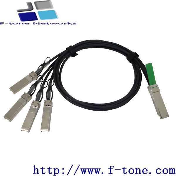
Hybrid Passive Copper QSFP+ to 4x SFP+
40G QSFP+ to 4x 10G SFP+ Direct Attach Passive Copper Cables
Features
- Hybrid cable conforms to the Small Form Factor SFF-8436 and SFF-8431
- Support for multi-gigabit data rates :1.0 Gbps - 10.3125 Gbps (per channel)
- Maximum aggregate data rate: 41.25 Gbps (4 x 10.3125Gbit/s)
- Hybrid cable link length up to 5m (passive limiting)
- High-Density QSFP 38-PIN and 4x SFP 20-PIN Connector
- Power Supply :+3.3V
- Low power consumption: 0.02 W (typ.)
- Temperature Range: 0~ 70 °C
Applications
40G QSFP+ to 4×10SFP+
- 10G/40Gigabit Ethernet
- InfiniBand SDR, DDR, QDR
- Switches, Routers, and HBAs
- Data Centers
- Fibre Channel
STANDARDS COMPLIANCE
QSFP+
- SFF-8436
- QDR InfiniBand
- QSFP+ MSA
- RoHS Compliant
SFP+
- SFF-8431
- SFP+ MSA
- RoHS Compatible
Product Description
The QSFP+ to 4x SFP+ Passive cable assemblies are high performance,cost effective for SFP+ and QSFP+ equipment interconnects . The Hybrid cables are compliant with SFF-8436 and SFF-8431 specifications. It is offer a low power consumption,short reach interconnect applications. The cable each lane is capable of transmitting data at rates up to 10Gb/s ,providing an aggregated rate of 40Gb/s.
Recommended Operating Conditions
|
Parameter |
Symbol |
Min |
Typical |
Max |
Unit |
|
Storage Ambient Temperature |
-40 |
+85 |
°C |
||
|
Operating Case Temperature |
Tc |
0 |
+70 |
°C |
|
|
Power Supply Voltage |
VCC3 |
3.14 |
3.3 |
3.47 |
V |
|
Power Dissipation |
PD |
0.02 |
W |
QSFP+ Pin Descriptions
|
Pin |
Logic |
Symbol |
Name/Description |
Notes |
|
1 |
GND |
Ground |
1 |
|
|
2 |
CML-I |
Tx2n |
Transmitter Inverted Data Input |
|
|
3 |
CML-I |
Tx2p |
Transmitter Non-Inverted Data Input |
|
|
4 |
GND |
Ground |
1 |
|
|
5 |
CML-I |
Tx4n |
Transmitter Inverted Data Input |
|
|
6 |
CML-I |
Tx4p |
Transmitter Non-Inverted Data Input |
|
|
7 |
GND |
Ground |
1 |
|
|
8 |
LVTTL-I |
ModSelL |
Module Select |
|
|
9 |
LVTTL-I |
ResetL |
Module Reset |
|
|
10 |
Vcc Rx |
+3.3V Power Supply Receiver |
2 |
|
|
11 |
LVCMOSI/O |
SCL |
2-wire serial interface clock |
|
|
12 |
LVCMOSI/O |
SDA |
2-wire serial interface data |
|
|
13 |
GND |
Ground |
1 |
|
|
14 |
CML-O |
Rx3p |
Receiver Non-Inverted Data Output |
|
|
15 |
CML-O |
Rx3n |
Receiver Inverted Data Output |
|
|
16 |
GND |
Ground |
1 |
|
|
17 |
CML-O |
Rx1p |
Receiver Non-Inverted Data Output |
|
|
18 |
CML-O |
Rx1n |
Receiver Inverted Data Output |
|
|
19 |
GND |
Ground |
1 |
|
|
20 |
GND |
Ground |
1 |
|
|
21 |
CML-O |
Rx2n |
Receiver Inverted Data Output |
|
|
22 |
CML-O |
Rx2p |
Receiver Non-Inverted Data Output |
|
|
23 |
GND |
Ground |
1 |
|
|
24 |
CML-O |
Rx4n |
Receiver Inverted Data Output |
|
|
25 |
CML-O |
Rx4p |
Receiver Non-Inverted Data Output |
|
|
26 |
GND |
Ground |
1 |
|
|
27 |
LVTTL-O |
ModPrsL |
Module Present |
|
|
28 |
LVTTL-O |
IntL |
Interrupt |
|
|
29 |
Vcc Tx |
+3.3V Power supply transmitter |
2 |
|
|
30 |
Vcc1 |
+3.3V Power supply |
2 |
|
|
31 |
LVTTL-I |
LPMode |
Low Power Mode |
|
|
32 |
GND |
Ground |
1 |
|
|
33 |
CML-I |
Tx3p |
Transmitter Non-Inverted Data Input |
|
|
34 |
CML-I |
Tx3n |
Transmitter Inverted Data Input |
|
|
35 |
GND |
Ground |
1 |
|
|
36 |
CML-I |
Tx1p |
Transmitter Non-Inverted Data Input |
|
|
37 |
CML-I |
Tx1n |
Transmitter Inverted Data Input |
|
|
38 |
GND |
Ground |
1 |
Note 1: GND is the symbol for signal and supply (power) common for the QSFP+ module. All are common within the QSFP+ module and all module voltages are referenced to this potential unless otherwise noted. Connect these directly to the host board signal-common ground plane.
Note 2: Vcc Rx, Vcc1 and Vcc Tx are the receiver and transmitter power supplies and shall be applied concurrent- ly. Requirements defined for the host side of the Host Edge Card Connector are listed in Table 6. Recommended host board power supply filtering is shown in Figure 4. Vcc Rx Vcc1 and Vcc Tx may be internally connected with- in the QSFP+ Module module in any combination. The connector pins are each rated for a maximum current of 500 mA.
SFP+ Pin Descriptions
|
Pin |
Logic |
Symbol |
Name/Description |
Notes |
|
1 |
VeeT
|
Transmitter Ground
|
||
|
2 |
LV-TTL-O |
TX_Fault |
N/A |
1 |
|
3 |
LV-TTL-I |
TX_DIS |
Transmitter Disable |
2 |
|
4 |
LV-TTL-I/O |
SDA |
Tow Wire Serial Data |
|
|
5 |
LV-TTL-I |
SCL |
Tow Wire Serial Clock |
|
|
6 |
MOD_DEF0 |
Module present, connect to VeeT |
||
|
7 |
LV-TTL-I |
RS0 |
N/A |
1 |
|
8 |
LV-TTL-O |
LOS |
LOS of Signal |
2 |
|
9 |
LV-TTL-I |
RS1 |
N/A |
1 |
|
10 |
VeeR |
Reciever Ground |
||
|
11 |
VeeR |
Reciever Ground |
||
|
12 |
CML-O |
RD- |
Reciever Data Inverted |
|
|
13 |
CML-O |
RD+ |
Reciever Data Non-Inverted |
|
|
14 |
VeeR |
Reciever Ground |
||
|
15 |
VccR |
Reciever Supply 3.3V |
||
|
16 |
VccT |
Transmitter Supply 3.3V |
||
|
17 |
VeeT |
Transmitter Ground |
||
|
18 |
CML-I |
TD+ |
Transmitter Data Non-Inverted |
|
|
19 |
CML_I |
TD- |
Transmitter Data Inverted |
|
|
20 |
VeeT |
Transmitter Ground |
1. Signals not supported in SFP+ Copper pulled-down to VeeT with 30K ohms resistor
2. Passive cable assemblies do not support LOS and TX_DIS
Ordering information
|
Part Number |
Product Description |
|
QSFP-4SFPPC-01 |
QSFP+ To 4X SFP+ Direct Attach Cables, 1m (30AWG),0ºC ~ +70ºC |
|
QSFP-4SFPPC-03 |
QSFP+ To 4X SFP+ Direct Attach Cables, 3m (30AWG),0ºC ~ +70ºC |
|
QSFP-4SFPPC-04 |
QSFP+ To 4X SFP+ Direct Attach Cables, 5m (28AWG),0ºC ~ +70ºC |
Important Notice
Performance figures, data and any illustrative material provided in this data sheet are typical and must be specifically confirmed in writing by F-tone before they become applicable to any particular order or contract. In accordance with the F-tone policy of continuous improvement specifications may change without notice. The publication of information in this data sheet does not imply freedom from patent or other protective rights of F-tone or others. Further details are available from any F-tone sales representative.